|
| Application |
|
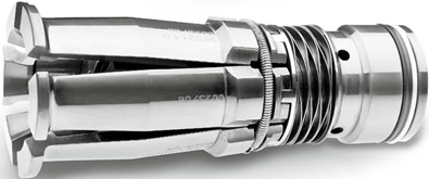
Pull studs are designed for screwing into steep taper tool
shanks, workpiece holders and pallets. In conjunction with SSK grippers
they are intended for drawing in and ejecting the above mentioned
machine elements.
Design features
AZB pull studs correspond to the values prescribed in the DIN,
ANSI, ISO, MAS and JIS standards with regards to their dimensions,
surface quality, hardness and strength values.
Abbreviation
FS max kN Clamping force
Ordering example
AZB 40 DIN
Delivery scope
Pull studs as per data sheet
Comments
Special designs are available for machine specific applications.
#workholding |
|
|
| Pull studs |
| Technical data |
| Type |
d1
-0,1 |
d2
-0,1 |
d3
-0,2 |
d4
g6 |
d5 |
d6
+0,1 |
l1 |
l2
±0,1 |
l3
±0,1 |
l4 |
l5 |
S
-0,1 |
FS max
kN |
| AZB 30/1 DIN |
13 |
9 |
17 |
13 |
M 12 |
- |
44 |
24 |
19 |
15 |
4 |
14 |
10 |
| AZB 40 DIN |
19 |
14 |
23 |
17 |
M 16 |
7,0 |
54 |
26 |
20 |
21 |
4 |
19 |
18 |
| AZB 45 DIN |
23 |
17 |
30 |
21 |
M 20 |
9,5 |
65 |
30 |
23 |
27 |
5 |
24 |
25 |
| AZB 50 DIN |
28 |
21 |
36 |
36 |
M 24 |
11,5 |
74 |
34 |
25 |
30 |
5 |
30 |
35 |
| AZB 60/1 DIN |
40 |
30 |
52 |
52 |
M 30 |
14,0 |
90 |
40 |
30 |
37 |
6 |
46 |
70 |
|
| For modifications all rights reserved |
|
| Pull studs |
| Technical data |
| Type |
d1
0
-0,3 |
d2
0
-0,3 |
d3 |
d4
h6 |
d5 |
d6 |
l1 |
l2
0
-0,3 |
l3
0
-0,3 |
l4 |
l5
0
-0,5 |
l7
0
-0,5 |
S |
FS max
kN |
| AZB 30 ISO-B |
13,35 |
9,30 |
17,0 - 0,5 |
13 |
M 12 |
4,00 |
34,0 |
11,80 |
8,15 |
17,20 |
2,75 |
1,25 |
14 - 0,27 |
10 |
| AZB 40 ISO-B |
18,95 |
12,95 |
22,5 - 1,0 |
17 |
M 16 |
7,35 |
44,5 |
16,40 |
11,15 |
21,10 |
3,25 |
1,75 |
18 - 0,33 |
18 |
| AZB 45 ISO-B |
24,05 |
16,30 |
30,0 - 1,0 |
21 |
M 20 |
9,25 |
56,0 |
20,95 |
14,85 |
27,05 |
4,25 |
2,25 |
24 - 0,39 |
25 |
| AZB 50 ISO-B |
29,10 |
19,60 |
37,0 - 1,0 |
25 |
M 24 |
11,55 |
65,5 |
25,55 |
17,95 |
29,95 |
5,25 |
2,75 |
30 - 0,65 |
35 |
| AZB 60/1 ISO-B |
37,25 |
24,95 |
50,0 - 2,0 |
32 |
M 30 |
14,00 |
88,0 |
38,15 |
27,65 |
37,00 |
7,75 |
3,75 |
36 - 0,75 |
70 |
|
|
|
| Pull studs |
| Technical data |
| Type |
α
± 15'
|
d1
-0,1 |
d2
-0,1 |
d3
-0,2 |
d4
h7 |
d5 |
l1 |
l2
-0,1 |
l3
-0,1 |
l4 |
l5
-0,1 |
l6 |
l7 |
R |
S
-0,35 |
FSmax
KN |
| AZB P30T-I |
45° |
11 |
7,0 |
16,5 |
12,5 |
M 12 |
43 |
23 |
18,0 |
16 |
5 |
3,5 |
2,5 |
2 |
13 |
10 |
| AZB P30T-II |
30° |
11 |
7,0 |
16,5 |
12,5 |
M 12 |
43 |
23 |
18,0 |
16 |
5 |
3,5 |
2,5 |
2 |
13 |
10 |
| AZB P35T-I |
45° |
13 |
8,5 |
20,0 |
12,5 |
M 12 |
48 |
28 |
22,5 |
16 |
5 |
3,5 |
2,5 |
2 |
17 |
12 |
| AZB P35T-II |
30° |
13 |
8,5 |
20,0 |
12,5 |
M 12 |
48 |
28 |
22,5 |
16 |
5 |
3,5 |
2,5 |
2 |
17 |
12 |
| AZB P40T-I |
45° |
15 |
10,0 |
23,0 |
17,0 |
M 16 |
60 |
35 |
28,0 |
20 |
6 |
4,0 |
4,0 |
3 |
19 |
18 |
| AZB P40T-II |
30° |
15 |
10,0 |
23,0 |
17,0 |
M 16 |
60 |
35 |
28,0 |
20 |
6 |
4,0 |
4,0 |
3 |
19 |
18 |
| AZB P45T-I |
45° |
19 |
14,0 |
31,0 |
21,0 |
M 20 |
70 |
40 |
31,0 |
24 |
8 |
6,0 |
5,0 |
4 |
24 |
25 |
| AZB P45T-II |
30° |
19 |
14,0 |
31,0 |
21,0 |
M 20 |
70 |
40 |
31,0 |
24 |
8 |
6,0 |
5,0 |
4 |
24 |
25 |
| AZB P50T-I |
45° |
23 |
17,0 |
38,0 |
25,0 |
M 24 |
85 |
45 |
35,0 |
32 |
10 |
8,0 |
5,0 |
5 |
30 |
35 |
| AZB P50T-II |
30° |
23 |
17,0 |
38,0 |
25,0 |
M 24 |
85 |
45 |
35,0 |
32 |
10 |
8,0 |
5,0 |
5 |
30 |
35 |
| AZB P55T-I |
45° |
32 |
24,0 |
48,0 |
31,0 |
M 30 |
115 |
65 |
53,0 |
40 |
14 |
11,0 |
7,0 |
5 |
41 |
50 |
| AZB P55T-II |
30° |
32 |
24,0 |
48,0 |
31,0 |
M 30 |
115 |
65 |
53,0 |
40 |
14 |
11,0 |
7,0 |
5 |
41 |
50 |
| AZB P60T-I |
45° |
32 |
24,0 |
56,0 |
31,0 |
M 30 |
115 |
65 |
53,0 |
40 |
14 |
11,0 |
7,0 |
5 |
46 |
50 |
| AZB P60T-II |
30° |
32 |
24,0 |
56,0 |
31,0 |
M 30 |
115 |
65 |
53,0 |
40 |
14 |
11,0 |
7,0 |
5 |
46 |
50 |
|
|
| Type |
d1
-0,1 |
d2
-0,1 |
d3
-0,2 |
d4
h7 |
d5 |
d6 |
l1 |
l2
-0,1 |
l3
-0,1 |
l4 |
l5
-0,1 |
l6 |
l7 |
R |
S
-0,35 |
FS max
kN |
| AZB 30JIS |
12 |
8 |
16,5 |
12,5 |
M 12 |
4,0 |
43 |
23,4 |
18,4 |
15,6 |
5 |
2 |
3,5 |
2 |
13 |
10 |
| AZB 35JIS |
15 |
11 |
20,0 |
12,5 |
M 12 |
5,0 |
44 |
24,0 |
19,0 |
16,0 |
5 |
2 |
3,5 |
2 |
17 |
12 |
| AZB 40JIS |
19 |
14 |
23,0 |
17,0 |
M 16 |
7,0 |
54 |
29,0 |
23,0 |
20,0 |
7 |
3 |
5,0 |
3 |
19 |
18 |
| AZB 45JIS |
23 |
17 |
31,0 |
21,0 |
M 20 |
8,5 |
60 |
30,0 |
23,0 |
24,0 |
7 |
4 |
5,0 |
4 |
24 |
25 |
| AZB 50JIS |
28 |
21 |
38,0 |
25,0 |
M 24 |
10,0 |
74 |
34,0 |
25,0 |
32,0 |
7 |
5 |
5,0 |
5 |
30 |
35 |
| AZB 55JIS |
36 |
27 |
48,0 |
31,0 |
M 30 |
12,0 |
98 |
48,0 |
36,0 |
40,0 |
11 |
5 |
8,0 |
5 |
41 |
70 |
| AZB 60JIS |
36 |
27 |
48,0 |
31,0 |
M 30 |
12,0 |
98 |
48,0 |
36,0 |
40,0 |
11 |
5 |
8,0 |
5 |
41 |
70 |
|
|
| Type |
α |
d1
-0,1 |
d2
-0,1 |
d3
-0,2 |
d4
-0,025 |
d5 |
l1 |
l2
-0,1 |
l3
-0,1 |
l4 |
l5 |
l6 |
R |
S
-0,1 |
FS max
kN |
| AZB 10JBS-I |
15° |
6,0 |
4 |
8,5 |
5,5 |
M 5 |
20 |
10,5 |
7,5 |
7,5 |
2,0 |
1,7 |
1,0 |
7 |
1,2 |
| AZB 10JBS-II |
0° |
6,0 |
4 |
8,5 |
5,5 |
M 5 |
20 |
10,5 |
7,5 |
7,5 |
2,0 |
1,7 |
1,0 |
7 |
1,2 |
| AZB 15JBS-I |
45° |
7,0 |
5 |
10,0 |
7,0 |
M 6 |
23 |
12,0 |
8,5 |
9,0 |
3,0 |
2,0 |
1,2 |
9 |
1,7 |
| AZB 15JBS-II |
0° |
7,0 |
5 |
10,0 |
7,0 |
M 6 |
23 |
12,0 |
8,5 |
9,0 |
3,0 |
2,0 |
1,2 |
9 |
1,7 |
| AZB 20JBS-I |
45° |
8,5 |
6 |
11,0 |
7,0 |
M 6 |
25 |
14,0 |
10,0 |
9,0 |
3,5 |
2,2 |
1,2 |
9 |
3,0 |
| AZB 20JBS-II |
0° |
8,5 |
6 |
11,0 |
7,0 |
M 6 |
25 |
14,0 |
10,0 |
9,0 |
3,5 |
2,2 |
1,2 |
9 |
3,0 |
| AZB 25JBS-I |
45° |
10,0 |
7 |
12,0 |
9,0 |
M 8 |
28 |
16,0 |
11,5 |
10,0 |
3,5 |
2,2 |
1,6 |
10 |
3,0 |
| AZB 25JBS-II |
0° |
10,0 |
7 |
12,0 |
9,0 |
M 8 |
28 |
16,0 |
11,5 |
10,0 |
3,5 |
2,2 |
1,6 |
10 |
3,0 |
|
|